Every road across the canal must have a bridge. One of the principle innovators of canal bridges was Squire Whipple, a graduate of Union College class of 1830. His influential Bowstring Bridge relied on a scientific system of mathematical equations. Based on the compressive and tensile strengths of metals -- that is the pressure they can take when squeezed, and the pressure they can take when stretched -- these equations predict with mathematical precision, what the thickness and shape of the metal components used for the bridge must be in order to support a given weight. His mathematics eliminated the guesswork and enabled engineers to safely use much thinner pieces of metal in their bridge construction than had previously been used. This reduced costs and increased reliability, allowing iron to replace wood as the principal load-bearing material for bridges.
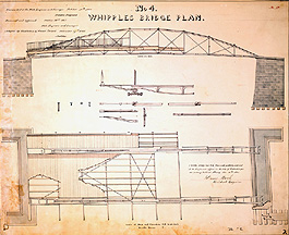
This is a generic plan for a Whipple Patent Bridge. This drawing indicates the metal work in blue, and the wood in yellow. The drawing at the top shows the major elements of Whipple's design. Cast-iron arches form a bow over the deck, and rather than being buttressed at the end with strong piers anchored in the ground, the bow is held together by a bowstring stretching across the bottom like an archer's bow. This bowstring is made up of a series of links connected in a paperclip fashion. The bowstring is attached to the bow by diagonal struts that pull it up against the vertical tie rods, forming a rigid grid. The road or deck is directly supported by the bowstring below, and the struts transfer the road's load to the arch above. This design makes buttressing the arches at the banks unnecessary.
 Whipple's second innovation in this bridge design is the
independence of the iron arches, which are not joined at the top and do not depend on the
roadbed for structural strength. The lateral strength of these arches -- the reason they do not tip
sideways -- is that they are wide at their base and narrow at their top, as can be seen in the lower
part of the drawing above.
Whipple's second innovation in this bridge design is the
independence of the iron arches, which are not joined at the top and do not depend on the
roadbed for structural strength. The lateral strength of these arches -- the reason they do not tip
sideways -- is that they are wide at their base and narrow at their top, as can be seen in the lower
part of the drawing above.
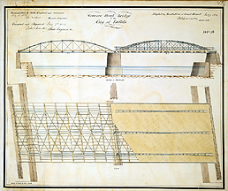
The bridge to the left is the Genesee Street bridge in Buffalo. This variation on the
classic Whipple design had two spans, and was designed to carry two lanes and two footpaths
over the river. The upper drawing shows the Whipple design for each span, with cast iron
arches, bowstring below and tie rods to create a rigid grid.
 The lower drawing shows the deck
bracing on the left and the planking on the right. Note that the abutments are designed to allow a
towpath on each side to pass under the bridge.
The lower drawing shows the deck
bracing on the left and the planking on the right. Note that the abutments are designed to allow a
towpath on each side to pass under the bridge.
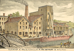
The lithograph to the right depicts both a busy canal-side grain elevator and two Whipple Bridges, one on the left and one in the far distance on the right. The characteristic cast iron, bow-shaped arches can be seen, and their stable shape -- wider at the bottom and narrower at the top -- is clearly depicted in the bridge on the left.
There were other types of bridges also used on the Erie Canal, each designed for a particular use: The Lift Bridge -- a low bridge designed to lift up out of the way of canal boat traffic; The Drawbridge -- a low bridge designed to move out of the way of canal boat traffic by drawing back into the road; and The Change Bridge -- designed to allow horses or mules to cross the canal when the towpath crosses from one side of the canal to the other. These are illustrated on The Bridge, page 2.
http://www.eriecanal.org/UnionCollege/The_Bridge.html