A Lift Bridge is a low bridge designed to lift up out of the way of canal boat traffic. This short bridge carried the towpath over a canal slip, a small canal perpendicular to the main canal, built to provide access to docking areas or mills. A closed lift bridge would enable traffic to cross the Canal at the same grade as the towpath compared to the slope on either side of a regular bridge. Since the slip was used much less frequently than the canal itself, the bridge was only open occasionally and traffic was rarely affected. Lift bridges also were used in cities where it was inconvenient to raise street levels to cross the canal.
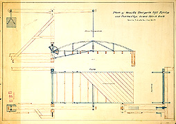
This lift bridge was designed by Abram Swartz and built in Black Rock. The side elevation drawing at the top shows a lift beam which pivots on a post with a counter-weight at the left to offset the weight of the bridge and make it easy to raise. A crank on the small gear at the left would engage the large gear which in turn pushed the lever which raised the bridge, assisted by the counter-weight. The bridge pivoted on an axle, shown on the left of the plan at the bottom. The plan also shows the lift beam and connecting rod attached only on one side of the bridge. This enables the tow rope to slide over the railing on the other side of the bridge.
 A Drawbridge is a low bridge designed to move out of the way of canal boat
traffic by drawing back into the road to let canal boats pass.
A Drawbridge is a low bridge designed to move out of the way of canal boat
traffic by drawing back into the road to let canal boats pass.
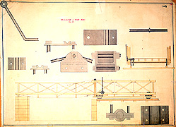
This drawbridge is a combination truss and suspension design, with cables running over a central post supporting the bridge on either side. The top half of this drawing contains illustrations of the cables and how they attach to the bridge. Suspension engineering was rare but not unknown in bridges on the Erie Canal. This bridge rolled back on wheels that sat on rails. A lever, shown on the right side of the bridge turned a gear attached to a fly wheel. This turned an axle that started the wheels of the bridge turning.
"Low bridge, everybody down" on the original canal was the shouted warning to people on the boat deck because the bridges were just a few feet above the canal, but it was soon apparent that low bridges had to be raised. As commerce along the canal developed and towns grew, additional bridges such as Whipple, lift bridges, and draw bridges were constructed.
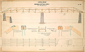
This bridge was built in Buffalo. It is a double-span truss bridge, built of wood. It needed a central pier, an unusual feature for a change bridge. The piers on each side are footed with wood, but the central pier rests on the gravel of the canal-bed.
The trussed sides, which support the weight of the roadway, are braced with sets of two converging iron rods. The bridge features a high roadway that bisects the truss providing greater stability to the structure. It also features railings designed to help the towrope slide easily over, without snagging. This bridge was also designed with special ironwork to make it easy for the rope to slide off each end. The drawings on the left and right in the middle show how this metal work is attached to the woodwork. On the right, the nut and bolt can stick out, but on the left, the nut and bolt are arranged so that the rope can pass smoothly over the top because the rope only slides over the railing on that side of the bridge.
http://www.eriecanal.org/UnionCollege/The_Bridge2.html