A lock enables a boat to pass from a section of canal at one water level to another section at a different water level. Locks also separate two sections of canal so that water from the upper level does not flood the lower level. A boat going from a lower level to a higher level enters the lock through the lower gates, which are then closed by a lock tender. The tender then opens a valve in the upper gates, admitting water to the lock and raising the boat. When the water level in the lock equals the level in the higher section of canal, the tender opens the upper gate, and the boat continues its journey. In the opposite direction, a boat enters the lock through the upper gates. The gates are then closed, the water level is lowered to the level of the water in the canal below, and the lower gates are opened to release the boat into the canal.
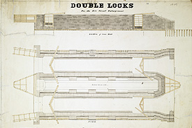
This drawing is a generic plan for a set of double locks. The top diagram shows the elevation of the inside of the lock wall viewed from the side. The gates are open and swung flat against the wall. The bottom section of the gates is colored dark gray, to represent the valves which were opened to let water through.
The center diagram shows the plan of the locks viewed from the top. The gates are closed on the left and shown partly open in each lock on the right. This diagram shows the recess in the wall into which the gates fit when opened. For strength, the gates close at an angle pointed upstream. Shown at the right are triangular features called mitre sills, heavy, braced beams located at the bottom of the canal against which the gates rest when closed.
The locks open and close using large tapered beams called balance beams, attached to the lock gates, shown in the top and center drawings.
At the bottom on the left is a view of the wooden pier in front of the lock viewed from the side, and at the bottom on the right is the lock viewed end-on without its gates, from the perspective of an entering boat.
The lock is stone resting on a wooden footing. This footing rests on wooden piles driven deep into the ground, as shown at the upper right. The planks shown at the top and bottom of the middle drawing represent this wooden footing on which the stonework rests. The stone sides of the locks are thicker at the end and buttressed in three places along the side.
At each lock, a lock tender operated the gates and controlled the small doors in the bottom of the gates to gradually fill and empty the lock. Even though the gates were angled upstream so that the flow of the river would force the gates together, leakage was still very considerable.
The Erie Canal required 83 locks, which were built of wood, wood and stone, stone, or reinforced concrete. The wooden locks, not unexpectedly, deteriorated rapidly and had to be replaced. The lock dimensions of the original canal were 90 ft. by 15 ft. to accommodate barges which were 7 ft. wide, 61 ft. long and required a 3 1/2 ft. draft. Very soon after the opening of the canal, it was apparent that single locks significantly impeded the flow of traffic, and in 1832 an enlargement was planned to replace the single locks with double locks and increase the lock size to 110 ft. by 18 ft. Double locks, such as the one shown above, enable traffic to proceed in both directions simultaneously.
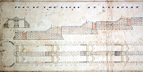 A flight of locks works the same way as a single lock, with each emptying into the next.
However, as shown in this drawing, the top locks contain valves in the stonework in their sides,
not in their gates; only the bottom gate has a hole in its bottom panel for a valve. This was done
to enable each lock to fill or empty independently of the rest of the flight. Since the bottom
gates of one lock are the top gates of the next, the only way to fill adjacent locks using the
traditional valves in the gates would be to open all the gates above or below to raise or lower the
water level in one lock. This would greatly limit the efficiency of the flight, as only one boat
could pass through the whole flight at a time. By using valves in the stonework on the side of
the locks, it was possible to control the water flow to each lock independently.
A flight of locks works the same way as a single lock, with each emptying into the next.
However, as shown in this drawing, the top locks contain valves in the stonework in their sides,
not in their gates; only the bottom gate has a hole in its bottom panel for a valve. This was done
to enable each lock to fill or empty independently of the rest of the flight. Since the bottom
gates of one lock are the top gates of the next, the only way to fill adjacent locks using the
traditional valves in the gates would be to open all the gates above or below to raise or lower the
water level in one lock. This would greatly limit the efficiency of the flight, as only one boat
could pass through the whole flight at a time. By using valves in the stonework on the side of
the locks, it was possible to control the water flow to each lock independently.
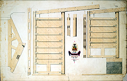 |
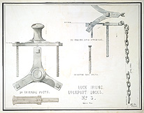
Left - Lock Gates Right - Lock Irons |
 |
The following is an excerpt from the Diary of Jonathan Pearson:
Thursday, July 25, 1833
"While the boat was passing thro the locks I had abundant time to go to the village and visit most
of the curiosities."
http://www.eriecanal.org/UnionCollege/The_Lock.html