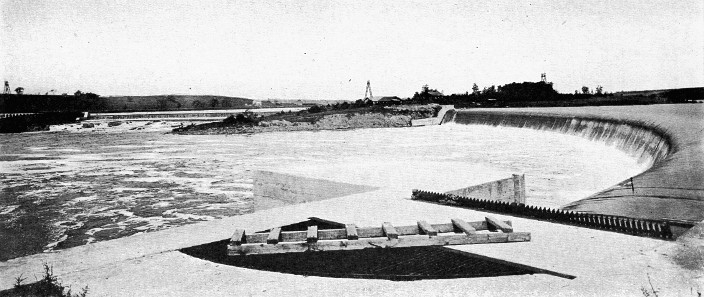
Large fixed dam, known as Crescent dam, at the foot of Mohawk river navigation. View from beside the power-house, showing the whole sweep of 1,922 feet of length, with the head-gates at the extreme left and the intervening island in the middle.
High Rank of Barge Canal as an Engineering Work -- General Features of Locks -- Siphon Lock -- High Lift Lock at Little Falls -- Tandem Locks at Lockport -- Large Fixed Dams in Mohawk at Crescent and Vischer Ferry -- Movable Dams: Bridge Type: Taintor Gate Type: Submersible Sector Gate Type -- Siphon Spillway -- Automatic Crest on Dam -- Concrete Troughs for Carrying Canal -- Noteworthy Section near Waterford -- Canal and Railroad Construction at Rome -- Complicated Situation at Rochester -- Interesting Problem at Medina.
"Having had the opportunity, through the courtesy of the State Engineer, of seeing practically all the main canal and its principal branches," said a visiting Federal engineer, "I can say without reservation that in no other area of the same extent in the world, including the Panama canal, can an engineer find so much of interest and instructive value in the matter of various types of canalization work. It surprises one after such an inspection that there is not a more general knowledge throughout the country of the canal, its construction and commercial probabilities." 1
Speaking editorially of the Book of Plans, New York State Barge Canal, a publication issued by State Engineer Williams particularly for the use of the engineering profession, the Engineering News-Record said in its issue of April 28, 1921, "Whatever be the opinion regarding the New York State Barge Canal as an economic factor there can be no doubt of its high standing as a work of engineering. With few exceptions its structures have been models of detail design which may well be set up as standards for future shipping canal work. ... Too infrequently are the structural records of big projects preserved in such convenient form."
The high rank of the Barge canal as an engineering work is attested also by many other competent judges. It does not seem necessary in the present volume, however, for the historian to exercise his character as engineer and discourse either at length or in technical phrase on the many engineering achievements of the enterprise. Much has already been written concerning these features, in both professional and popular style, and accordingly there is no need for long repetitions. Moreover for the engineer there is the Book of Plans, which often gives in a single drawing what a multiplicity of words cannot so well describe. But this volume would not be complete without at least a brief mention of various engineering features and therefore a few of the salient facts are noticed.
There are 35 locks on the Erie branch of the Barge canal, 11 on the Champlain, 7 on the Oswego and 4 on the Cayuga and Seneca. The standard length of lock chamber is 310 feet at the center, but 10 feet of this is taken up by the concaved lower face of the wall bounding the upper end of the chamber. The distances between gates vary with certain conditions, the least being about 338 feet. The locks are 45 feet wide in general and have 12 feet of water over the sills. The maximum parallelogram which can be passed through all the locks would be 300 feet long by 44.44 feet wide. There are two guard-locks, one on each side of the crossing of the Genesee river. These locks have lift gates, placed 311 feet apart, which are of the same type as the guard-gates. They have the usual width and depth of water, 45 and 12 feet, respectively, but no normal lifts.
The Barge canal locks are built of concrete throughout, both side and cross walls and floor. At a few points, where favorable rock was encountered, the concrete floor has been dispensed with. The side walls are 5, 6 or 7 feet wide at the top, according to local circumstances, and vary in height and bottom width with the lift of the lock and certain other conditions. In some cases, where one side of a lock is exposed to a river channel, the top width is increased to 12 feet. The lifts range from 6 feet to 40 1/2 feet. Both the differences of lift and the fluctuations between normal and high navigable stages govern the heights of the side walls, which vary from 28 feet to 61 feet, with an extreme at one point of the lock at Little Falls of 80 feet. The bottom widths of these walls, which range between 13 and 34 feet, are determined by the height of the walls, the nature of the foundation and certain incidentals of design at each lock. Unless a rock or hardpan foundation could be obtained, piles were driven under practically all locks.
Within each side wall runs a culvert for filling and emptying the lock. The culverts are connected with ports that open into the chamber at the bottom of the walls. These culverts vary in size, the dimensions being 5 by 7 for locks of 12 feet lift or less, 6 by 8 feet for lifts between 12 and 23 feet, and 7 by 9 feet when the lift is 23 feet or more. Connected with the 5 by 7 culverts are 16 ports, 8 on either side, while the number is increased to 22 with the 6 by 8 culverts and 28 with the 7 by 9 size. The ports have been made both by imbedding cast-iron pipes in the concrete and by leaving rectangular openings in the walls, the latter being the later method. The area of opening in either case is about 7 1/2 square feet each.
In some of the locks there is another culvert through one of the side walls -- a feature of the hydro-electric development for operating and lighting the locks. Local conditions and the proximity of two or more locks have determined where these power-plants shall be placed. At some points one plant serves several locks, as at Waterford, where a series of five locks and two guard-gates receive power from the plant at Crescent dam.
The lock gates are of the mitering, girder type, carrying the principal load as beams. In general they are built of steel, with single skin-plates, but have white oak quoin and toe posts. The quoin post swings on a cast-steel pivot, set in the concrete, and is held at the top by an adjustable anchorage. The bearing is against cast-iron quoin plates set into the side walls. Wooden gates are employed at three locks.
The lock gates are each opened and closed by a steel spar equipped with a rack, actuated by a 7-horse-power motor acting through a train of gears. This spar is also equipped with a heavy coil spring, to absorb shock. To open or close the gates requires about one minute.
Movement of the gates is controlled from four operating stands, one near each gate. These operating stands are equipped with drum type master switches, by means of which magnet type controllers automatically regulate the acceleration and speed of the motors. Limit switches are provided to arrest the motion of the gates at each end of their travel.
Signal lights indicate to the operator the position of the gates. In the event of failure of power or damage to the motor, it is possible to disconnect the motor and operate the gates by hand by means of sweeps provided for this purpose, which have been so designed that but two men will be required for such operation.
The valves regulating the flow of water in the culverts are suspended on two chains, which pass over chain wheels near the top of the valve wells to cast-iron counterweights. The chain wheels are mounted on a shaft rotated by a motor operating through a train of gears designed to raise or lower the valves at a speed of about six feet per minute.
The motors of the 5 by 7 and 6 by 8 valves are rated at 3 horse-power while those operating the 7 by 9 valves are rated at 7 horse-power.
The movement of the valves is controlled in a manner similar to the movement of the gates and the master switches are located on the same operating stands. Signal lights indicate to the operator that the valves are fully open, two-thirds open, one-third open, or closed. Like the gate machinery the valve machinery may be operated by hand whenever this is necessary or desirable.
Electric capstans, on at each end of each lock, are provided to control the movement of boats along the approach walls and to tow them into and out of the lock chamber. A 20-horse-power motor operates each capstan at a speed of about 60 feet per minute with a pull of 8,000 pounds. The operation of these capstans is controlled by a magnet type controller and master switch located near the capstan.
All the motors incorporated in the lock operating machinery are of the mill type.
In general a power generating station has been installed for each lock. But if two locks are close together, one station suffices for both. In one instance a single station supplies power for five locks. These power stations, constructed of reinforced concrete, 20 by 30 feet in plan and about 20 feet high, are place adjacent or near the various locks.
The Barge canal has two or three noteworthy locks. In the city of Oswego there has been constructed a siphon lock -- the only lock of this type on the Barge canal, also the first to be built in this country and the largest employing the siphon principle yet built. The general design of the culverts is similar to that of a lock of ordinary type, except that at the upper and lower ends the culverts are curved up so as to form necks, or crowns, which rise a little above the highest water-level and which at the same time are shut off from all communication with the outer air except through the operating pipes. The flow of water is started in the siphons by means of tanks, one being built in each wall near the upper end and communicating through pipes with the upper and lower levels and with both siphons in the same wall and being shut off from all other communication with the outer air. To perform an operation the tank is first filled with water; then the intake valve is closed and the outlet opened. There results a body of water suspended by its weight but tending to escape into the lower pool, thus producing the necessary vacuum. On opening the air valve, air from the siphon rushes into the vacuum and water begins flowing over the crest in the neck. Using both siphons the lock chamber can be filled in from 4 1/2 to 5 minutes, while it can be emptied in from 5 1/2 to 6 minutes. It has been found that the draft of the siphon is such that soon after the flow has started the direction of the air is reversed and the vacuum is restored in the tank. Thus the operating power is self-renewing and, except for air leakage, lockages can be conducted by merely manipulating the 4-inch air valves.
At Little Falls there has been built a lock notable for its high lift -- 40 1/2 feet. The lower gate of this structure is of the lift type -- the only instance of lift gate on any Barge canal lock, except the guard-locks at the Genesee river crossing and the upper gate of the Utica terminal lock. Another novel feature at this lock is the side pool. Its purpose is to conserve the water-supply by storing water drawn from the upper half of a chamberful and discharging it to fill the lower half of the chamber at the next lockage. Still another unusual feature at this lock is the masonry across the chamber from side wall to side wall at the lower gate, under which boats must pass in entering the lock from below. At the time of beginning construction this was the lock of highest single lift ever undertaken in the world. This structure takes the place of three locks in the waterway which the Barge canal has just superseded. Before the original State canal was built a private company essayed to improve navigation at Little Falls, beginning work in April, 1793, and using five locks to overcome the fall in the river. As it happens, a lock constructed by this company, although built about seven years later, is still standing. The contrast between these two in such close proximity, the pigmy and the giant of New York canal history, is most striking. An excerpt from a report the directors of this company made to the Legislature in 1796 brings out this contrast. The facts are as interesting as the language is quaint. "Five locks," reads the report, "having each nearly 9 feet lift are placed towards the lower end of the Canal, and the pits, in which they are placed, have been excavated out of solid rock, of the hardest kind; the chamber of each lock is an area 74 feet by 12 feet in the cleave, and boats drawing three feet and an half of water may enter at all times."
On the earlier State canals the building of two or more locks end to end was not unusual. Combined locks they were called in those days. On the Barge canal there are only two instances of such locks -- tandem locks they are now generally termed. The more conspicuous of these is the pair at Lockport. Prior to Barge canal construction there were ten locks at Lockport, two flights side by side of five locks each. The southerly flight has now been demolished and two locks of Barge canal dimensions have been built in its place. The site of the locks at Lockport, from the time of the original canal to the present, has never changed. The early engineers found the logical location for locks in this vicinity and the same place has been in use ever since. The romance of ancient geological happenings attaches to this site. Where the locks now stand the rushing waters from the Great Lakes once poured, falling over a precipice and excavating the gorge through which the canal passes in its course to the east. In that far-off past this waterfall and gorge, formed by the floods from the interior, were a lesser counterpart of the great Niagara cataract and descended the same declivity, the formation known in geological phrase as the Niagara escarpment.
The two new locks at Lockport have a normal combined lift of 49 feet. At the upper end of the pair there are two sets of gates, one for emergency, since the canal level above extends to Lake Erie and these lock gates and the guard-gate at Pendleton are all that stand in the way of waters of the lake again rushing over the precipice as in the bygone ages. We shall see in the next chapter that a large volume of water is fed from Lake Erie into the western half of the canal. Much of this supply is carried around the Lockport locks in a tunnel and incidently valuable water-power is created. This is used for manufacturing. It was the creation of power from passing canal waters which brought Lockport into being. Before the original Erie canal was begun there was not even a hamlet where the city now stands, but in less than a year after construction had commenced at this locality a sizable village had sprung up.
Aside from the locks, the dams are usually the most important structures on any canal. On the Barge canal, as well as on modern canals in general, the dams are particularly important. This is due to the fact that in the present-day development of waterways it is the practice to canalize the rivers. This condition is particularly true of the Barge canal, which as a whole is distinctively a river canalization.
There are four dams of the fixed variety on the Barge canal which are outstanding because of their size. Two are river dams, located in the lower reaches of the Mohawk, and two are reservoir dams. The dam at the lower end of Mohawk river navigation, called Crescent dam from the name of a near-by hamlet, is situated just below the point where the land line from the Hudson enters the Mohawk. This dam is curved in plan, but is of the gravity type, not depending on its curved form for stability. This structure is made up really of two dams, with a rocky prominence intervening. One section spans the former river channel while the other crosses low land, which after completion was submerged. The entire structure sweeps through nearly a semicircle on a 700-foot radius, with a total length of 1,922 feet. Across the front of the dam built on the low land was constructed a third dam. This is lower in elevation and its purpose is to maintain a pool which may serve as a water-cushion to break the fall of water spilling over the crest and prevent erosion of the rock at the foot of the main dam. The pool back of the main dam has been raised some 27 or 28 feet above the former river level. This pool spreads out into a virtual lake. Indeed during the ceremonies attending the opening of this portion of the canal on May 15, 1915, Governor Whitman christened this body of water Lake Crescent. The crest of this dam stands 39 feet above the apron. At the base it is 42 feet wide and at the top, 11 feet 5 inches. The apron has a width of 40 feet. The masonry content is 54,360 cubic yards. At the eastern end, the end nearest the canal line, is situated the largest power-station as yet constructed on the canal. This station supplies current for operating the two guard-gates and the five locks of the Waterford series and for lighting this stretch of canal. At the western end there are provided head-gates.
Large fixed dam, known as Crescent dam, at the foot of Mohawk river navigation. View from beside the power-house, showing the whole sweep of 1,922 feet of length, with the head-gates at the extreme left and the intervening island in the middle.
About ten miles above the Crescent dam is the other large fixed dam of the canal, known as Vischer Ferry dam, this name also coming from a near-by hamlet. These two structures are much alike; the general design is the same and the dimensions do not differ widely. The site chosen for this dam was one having two river channels encircling an island of considerable size, which had steep shores and a rocky plateau-like top some twenty feet above the river. A dam was built in each of these channels, and connecting the two sections was a third section across the island, making one continuous crest of nearly two thousand feet. Each section is straight in plan and the trace of the whole structure is roughly that of a reversed letter Z. The crest of this dam is 36 feet above the apron; its bottom width is 40 feet 6 1/2 inches, its top width, 11 feet 5 inches, and the width of its apron 38 feet. It contains 58,750 cubic yards of concrete. With the immediately adjacent locks, one of Barge canal dimensions and 26 feet lift at one end and a temporary lock of old size at the other, the amount of masonry at this locality reached a total of 90,000 cubic yards. The small lock was needed to maintain navigation during a part of the time while construction was in progress and before the new channel both below and above the dam was completed. This dam too forms a lake of considerable size.
Descriptions of the Delta and Hinckley dams, the two prominent reservoir dams, are given in connection with the chapter on water-supply and so need not be included here.
We desire to speak of three types of movable dam in use on the Barge canal. The first is the kind known as the bridge dam with Boulé gates. This type, however , was described so fully in our study of early canal policies that little need now be added. There are eight of these bridge dams on the lower Mohawk. These are situated at Scotia, Rotterdam, Cranesville, Amsterdam, Tribes Hill, Yosts, Canajoharie and Fort Plain. Four of them have two spans and four have three spans, the various lengths of span being 150, 180, 210 and 240 feet. The total lengths of these structures range from 370 to 590 feet and the depth of water between sill and upper level varies from 16 to 20 feet. For operating these dams steam winches were tried at first but now electric winches have been supplied. A part of the dam across the Genesee at Rochester is of this type. Bridge dams, but smaller in size, are also located at Mohawk and Mays Point.
The general principles which governed the designing of the bridge dams were these: To reproduce the natural area of discharge at each site, so as to avoid changing flood heights; to use high dams, so as to reduce their number and length and therefore their cost; to use few pieces, so as to concentrate the strength and reduce the number of pieces to be handled; to place a minimum amount of steelwork permanently under water, because of rusting; to make all parts of plain workmanship and similar as far as practicable, and to incorporate only such features as had been successfully adopted elsewhere or concerning the success of which there appeared to be no reasonable doubt.
Another type of movable dam of which there are many examples on the Barge canal is the Taintor gate. This has been used in a wide variety of ways -- as a whole dam, as a regulating section in conjunction with a fixed dam, as a gate to fill a notch in a fixed dam, as a by-pass gate beside a lock, as a by-pass gate around a guard-gate, and as a crest across the top of a low fixed dam. An unusually large dam of this type has been built beside lock No. 1 of the Champlain canal, a short distance north of Waterford. It serves here as the regulating section in connection with a fixed dam and consists of six gates, each 50 feet wide in the clear and having a vertical height of 17 feet above the sill. A single gate of still longer span is that at Whitehall, where it forms the movable crest on a low fixed dam and is operated from a highway bridge which crosses the stream at this point. The clear length of this gate is 90 feet. The four other most conspicuous examples of Taintor gate are those at Cayuga and Waterloo, where the gates constitute the whole of the structures that act as regulating works for Cayuga and Seneca lakes, respectively, and those at Phoenix and Fulton, where they form regulating sections in conjunction with fixed dams and regulate the Oswego river.
The Taintor gate is a sector gate and also it is the usual form of sector gate, but for the Rochester dam a somewhat novel adaptation of this type was devised, for which, however, a name no more distinctive than submersible sector gate has been used. In the sector type of dam, it may be explained to the non-technical reader, the movable portion, when viewed in cross-section, forms the sector of a circle, of which the arc is the upstream face. The movable part is usually constructed of steel, the face being a solid plate. This gate is attached to and moves between abutments, piers or other suitable forms of masonry. In the Rochester dam the sector gate is pivoted at about the level of the stream bed on the downstream side rather than above the water-level of the upstream side, as is the usual Taintor gate. In passing water through the ordinary type the gate is raised and the water flows beneath. At the Rochester dam the gate is lowered into a recess in the masonry and the water flows over it. The dam across the river at Rochester is made up of two types, the longer portion being a bridge dam. The reason for making a part of it of the sector type and of this peculiar kind of sector is the presence in the river of much flood wood. This gate at Rochester always presents an unobstructed crest to the water in whatever position it happens to be, whether fully raised or fully lowered or at any point between. It thus becomes a clear and free but adjustable spillway. So that debris may find no lodgment after it passes the crest, a deck is provided on top of the sector-shaped ribs which support the face of the gate, this deck forming an inclined plane, down which the water may flow, and simply changing its angle of slope with the raising or lowering of the gate.
Aside from the locks and the dams there only two structures of which we desire now to speak, and one of these is really a type of dam. These are the siphon spillway and the automatic crest for a dam. Both these structures are new in the field of engineering and were developed in Barge canal design. The engineer who conceived them holds patents governing their use, but the State was not required to make any compensation.
The siphon spillway is a structure particularly fitted to localities where there is not room for the usual long overflow spillway but where it is essential nevertheless automatically to regulate the surface-level of a body of water within fixed limits and prevent it from rising much beyond a given elevation.
In many places the Barge canal receives the drainage from the land adjacent to the channel. As a widely fluctuating canal water-surface is to be avoided, if possible, it has been necessary to get rid of any surplus, and if this water at times may flow in rapidly it must be discharged with equal rapidity. Where conditions permit, this has been accomplished ordinarily by a waste-weir of sufficient length of spillway to pass the required amount in a given time. But when the volume is large the spillway must be long and sometimes conditions exist which make a long spillway undesirable or even impossible. It was the presence of such conditions, especially at Whitehall, one of the places where a siphon spillway has been built, that led to the designing and introduction of this new structure. It is believed that in this structure the siphon principle was used for the first time to create a spillway of any considerable size. The siphon action is entirely automatic, in both the starting and stopping of the flow. The reduction in length between this structure and an ordinary spillway varies with the available head of water, but the several spillways of this type on the canal accomplish as much as the old kind from three to five times their length. The economy in cost of building the siphon type is also considerable.
As the name implies, the surplus water is discharged through a siphon, or rather through the several siphons which are incorporated in each of the structures as they have been built on the Barge canal. These siphons are inclosed in a concrete wall, which, except for openings in its faces, differs little in outward appearance from any wall that might be built to separate two streams having different surface-levels. The siphon is simply a cavity in the wall. Its inlet is placed well below the surface of the stream to be regulated; its outlet is as low as the stream that carries away the flow will permit; its crown rises to the elevation at which it is desired that the discharge of water shall begin. On the canal the permissible surface fluctuations are not large, and as the siphon does not come into action until completely filled with water, it has been necessary to limit the height of the crown to the range of fluctuation at each particular locality, the necessary area being obtained by increasing the width at the crown. The bottom of the crown is at the low-water level and at this elevation vents pierce the wall from outer face to siphon. When the water has been drawn down to this level, air enters through these vents and stops the flow through the siphon. A little below these vents a precautionary vent is placed, to break the flow in case the upper openings become clogged. These are the essential features of the siphon spillway. In designing one, however, there are other details to be worked out, such as the flaring of the inlet to reduce loss of head due to entry, a screen at the inlet to prevent the entrance of floating bodies, the development of the siphon dimensions from a wide and low crown to more nearly square inlet and outlet, forms which may be removed after the concrete is poured and an ordinary spillway to act as a drift gap and carry off debris.
The second of the two structures we mentioned is an automatic crest on a dam. Only one of this type was built on the Barge canal. The masonry portion is much like an ordinary low dam, with abutments rising several feet above the crest. The movable part runs lengthwise along the whole masonry crest and has a close-fitting contact with each abutment. It is made chiefly of wood and consists of two leaves set at right angles and hinged at their intersection to the top of the masonry crest. These leaves are L-shaped in cross-section, the upper leg being slightly longer than the lower. On the downstream side of the masonry crest, directly beneath the hinge, is a recess in the masonry, in cross-section the sector of a circle, into which the major portion of the movable crest may drop, the whole of it swinging down below the level of the masonry crest. The lower leaf is prevented from rising entirely out of the recess, being stopped by a projecting steel plate along its upper edge. Several openings through the masonry connect this recess with the water above the dam. The principle of operation is that of unequal water pressure against the two leaves, the leaves being properly proportioned and carefully weighted in order to make the action automatic. In picturing the crest in action we shall assume that water above the dam is at the level of the masonry crest and is rising. The pressure against the lower leaf has raised the movable crest as high as it can go. As the water rises, the pressure against the upper and longer leaf gradually increases until it becomes equal to that against the lower leaf. A little beyond this point and the crest begins to swing down, going quickly once the water has begun to flow over. It drops completely below the masonry and allows the flood to pass before the pressure on the lower leaf raises it and brings it again into action.
In the western part of the state the canal in a few places is carried on the tops of rather high embankments. In these localities concrete troughs with bottoms and side walls of masonry have been built. These structures deserve a brief notice. Those constructed at first did not have the drainage features of the later style but otherwise were about the same. The trough was not designed to carry the whole weight of the water as an aqueduct would. Rather the underlying thought was to prevent serious leaks by not allowing leakage to get a start. The plan was very simple -- just two courses of concrete in the bottom of the prism with a layer of screened gravel between. In the gravel were laid lines of drain tile every twenty feet and on top of the upper course of concrete tar felt waterproofing was placed. The side walls, well joined to the bottom courses, were about of standard design except that inspection chambers six and a half feet high ran through them lengthwise and at the side of these chambers was a channel into which emptied the lines of drain tile. The side walls were well backed by embankments at least 22 feet wide at the top and sloping down on a one on three slope.
Aside from the individual structures there are also numerous localities on the Barge canal which during construction have presented such complex and difficult problems that a record of the solutions is of considerable interest, especially to the engineer. We cannot now describe all the places of this character, the list is too long, but briefly we may mention four -- Waterford, Rome, Rochester and Medina.
In all the story of transportation west from the Hudson river there has always been the difficulty of getting out of the river valley and up the first stage of the ascent. The early highways made it by steep climbing or lengthened windings. The waterway which preceded the first State canal, lying mainly in the Mohawk river channel, stopped at Schenectady and depended on wagons to deliver goods from the Hudson. The original Erie canal had locks so close together that frequent lockages set the boats aground. When the canal was enlarged the peril of grounding was overcome by longer levels, but still the many locks were a grievous trial to navigators and a hindrance to rapid movement. The first railroad mounted the acclivity by pulling its cars by ropes up a sharp incline before it began the overland journey under power of its locomotives. Later a gradually ascending route was adopted, but the long years of using extra locomotives for pushing trains have borne witness to the difficult situation.
It was this problem of getting out of the Hudson river valley that lay at the bottom of selecting the Waterford route for the Barge canal. After the locks had been relocated and rebuilt during the first canal enlargement no improvement was attempted until the period of the nine-foot deepening, when plans were made for a high pneumatic lock, designed to take the place of the sixteen ordinary locks near Cohoes. But that improvement came to an end with nothing done towards building the lock. In the two surveys which followed almost immediately -- the Deep Waterway and the preliminary Barge canal -- routes either beside or very close to the Cohoes falls were the only ones considered. It was after engineering forces for constructing the Barge canal were organized and sent into the field for additional data that the route along which the canal has been built was discovered. This route, which makes the passage from the Hudson to the Mohawk through a land line about two and a half miles long is so far from the falls, at least a mile at the nearest point, the it had escaped serious consideration earlier. Its advantages were so marked, however, that it was speedily adopted. It follows a natural valley to within a short distance of its upper end, but then it passes through a deep rock cutting. It enters the Mohawk above both the Cohoes falls and the dam of the Cohoes Company and also above the site of the new Crescent dam, which has created a pool above the land line for ten miles of river navigation.
Because the Waterford land line solved the problem of passing from the Hudson to the Mohawk and because its completed structures contain so much of engineering concern, it becomes a place of importance. On this short stretch a visitor may see more to interest him and a greater variety of structures than on any other portion of many times its length. The locks are not of the tandem variety, as the preliminary plans required, but have short pools between them. There are five of them and they constitute the greatest series of high lift locks in the world. The lifts vary from 32 1/2 to 34 1/2 feet and the aggregate is 169 feet. The distances between locks are so short that the pools had to be widened, so as to store sufficient water for frequent lockages. There are by-pass channels around all of these locks. An interesting type of concrete docking borders the channel in several of the pools. There are two guard-gates above the locks -- to protect both the canal line and the cities below. Without these guard-gates, were some accident to destroy a lock gate or tear out an embankment, all the stored waters of the Mohawk might come pouring out. Before the unprecedented flood of March, 1913, only one guard-gate stood at the head of this line, but from the experiences of that time the State Engineer, who himself watched through one night while the flow reached its maximum, was led to build a second guard-gate. These gates have Taintor gate by-passes around them. There are other features of note along the Waterford line, such as the great Crescent dam, the power-plant at its end for supplying the whole stretch with electric energy, the transmission line with its concrete poles, the three power substations, the deep rock cut, the high retaining walls and the several bridges, both railroad and highway.
The preliminary Barge canal survey considered two routes at Rome, one through the southern outskirts of the city and the other directly through the city, following the line of the existing canal for much of the way. The northerly route provided for a level higher than the other by several feet. The southerly route was crossed twice by the New York Central railroad necessitating two long four-track bridges. When, prior to construction in this vicinity, it came to making a final decision as to routes, there were three parties to the conference -- the State, the city and the railroad company. In most of its course through the Mohawk valley the railroad runs close to the north side. After crossing the old canal at Schenectady, it remained on the north side of the waterway as far west as Rome, where it crossed to the south side. The new canal, however, was to be crossed east of Utica and thence westerly the waterway could remain on the north side except for the possible crossing and recrossing at Rome. The northerly route, therefore, had the advantage of eliminating these two bridges, but it had the compensating disadvantages. The canal question, however, was not the only one at stake. There were several railroad features, irrespective of the canal, which entered into the consideration. The railroad had to swerve to the north and back again for the purpose of reaching Rome, rounding a very sharp curve to accomplish it. The station was old and sadly needed rebuilding and moreover it was on the wrong side of the tracks, passengers having to cross freight tracks at grade to reach the coaches. Most of the city crossings were at grade. The problem, thus complexly involved, awaited solution for some time before an agreement satisfactory to all concerned could be reached.
Finally the southerly canal route was chosen, but the railroad line was changed also, being thrown to the south of the canal. This meant a relocation of several miles of road, but the company gained a much better alignment by the change. The canal too was changed from the first line contemplated, being carried straight west to an intersection with the old canal at New London instead of circling to the north and meeting it at Fort Bull. Thus both the canal and the railroad were straightened and shortened and were taken out of the built-up portion of the city. But the work involved in all these changes and new structures was enormous and Rome became a busy center of canal activity as well as a place where much of interest could be seen. So far as costs were concerned there were no large differences between the various solutions of the problem.
If we were to visit the finished canal at Rome, we would find several important structures. At this point the waters from the Adirondack reservoirs are received. These come down through the Black River canal to the Delta reservoir, where a new and large impoundage has been provided for the Barge canal. Thence the augmented supply reaches the Rome level through the Mohawk river. The whole flow of the river is taken into the canal at this point. A retaining dam lies in the bed of the stream just above its entrance into the canal. Water not needed for feeding the land line sections to the east and west is spilled into the old river channel over two spillways, one near-by and the other at some distance away, towards the easterly end of the level. This water, however, is utilized for canal purposes farther downstream, for the canal occupies the river channel throughout most of its course eastward to the Hudson. There is a guard-gate at each end of the section of canal carrying the whole river flow. When desired, these gates confine the feed water to this section -- the common practice in winter and a possible action in all times of emergency. The new canal crosses the old at Rome but at a lower level. Since it has been necessary to keep open both portions of the old canal, a junction lock has been built on each side of the new channel, allowing old-sized boats to lock up into the old canal in either direction. The section of old Erie canal to the west has become in effect a part of the Black River canal, being needed to furnish a connection between that waterway and the Barge canal. But instead of cutting off the old Erie immediately west of its junction with the Black river canal, it remains open to the western border of the city, where a dam across the old prism stops further navigation. The section of the old Erie to the east is the portion which was retained under the terminal law and originally extended to Mohawk. A dive culvert, or inverted siphon, to feed this stretch, was built under the new channel at Rome. The detailed account of the Rome-Mohawk section is given elsewhere. Aside from the foregoing structures there have been a few bridges and some new highways and in connection with the railroad relocation there was the long new road-bed and a modern station for the city.
The early canal was the chief factor in building up the remarkable chain of cities and villages that spans New York state. Later came the railroads and also many other influences to complete the work, but it was the canal that fixed the locations and gave both the initial impulse and the controlling impetus toward growth. Thus it is that we find the old canal running through the centers of large cities. When it came to enlarging the channel to Barge canal dimensions, however, it was clearly seen that the expense of building the new waterway through these crowded cities was prohibitive. This and other reasons have turned the channel to the outskirts of the municipalities wherever possible. So it was with Rochester. Several routes in this vicinity were studied during the preliminary survey, but the authorizing law laid down the route circling the city on the south about as it has been built except that amendments later put the spur to the city in the Genesee river rather than in the old Genesee Valley canal.
The work at Rochester was the last large portion to be undertaken. This was not because the engineering problems could not be solved nor because choice had to be made between routes, but the citizens were opposing what the State was attempting to do and it was years before agreements could be reached. The delay in coming to terms with the railroads also retarded progress. If construction had been begun earlier in this vicinity, doubtless the whole canal could have been opened earlier, or at least it could have been opened without such almost superhuman efforts as were actually required for the accomplishment. When State Engineer Williams assumed office in 1915 he perceived that the Rochester problem had to be solved speedily or it would block the whole canal scheme. He attacked it with determination and the result was that as soon as money was forthcoming to begin construction again after the exhaustion of funds the work at Rochester started. But we are not concerned now with details of construction or policy and moreover they are discussed fully elsewhere. The large and rather complex work in the vicinity of Rochester has engineering interest and that is the feature which is taking our attention just at present.
The problem at Rochester was this: The canal could not well pass through the city, but there had to be some way for boats to enter as close to the business center as possible. A line somewhere along the southerly city borders appeared to be the most feasible route, and this in conjunction with a spur in the Genesee furnished access to the city. Except for complicated details this part of the problem was simple and had to be solved in accordance with certain specifications in the law. But the route to the south which seemed best, all things considered, involved passage through a city park, deep cutting in both earth and rock, high embankments, and six railroad crossings. Also the spur line in the river was bordered on each bank by a railroad, and moreover the river was subject to unusually high floods. It was the park, the railroads and the flood conditions that presented the more difficult engineering problems, but none of these was really serious, once the way was cleared for action.
By taking scrupulous care the engineers have not allowed the canal to spoil the beauty of the park. Ornamental bridges, both foot and highway, span its waters. Spoil-banks have been graded, fertilized, seeded and sodded. Dikes border the river and drains care for any possible seepage. A guard-lock stands on each side of the Genesee river crossing. The bulk of the work has been along the river, where long, high walls line the banks, and the railroads have been altered to fit changed conditions, a new passenger station having been provided in one instance. A commodious terminal, at the end of the spur, is in the very heart of the city. A convenient approach to the terminal was a work of considerable size and involving some interesting structures. The walls along the river have been built high enough to overtop any known flood, but to make assurance doubly sure provision has been made for placing flash-boards upon them in case of need. A movable dam at the lower end of the spur maintains the proper water-level for both the spur and the main canal at the river crossing. This dam is made up of two types, the bridge dam and the submersible sector gate, both of which have already been described. The new dam is situated a little below an old dam, which has been left intact. When the new dam is not in operation, former conditions, except for deepened channel and wall-lined banks, will be exactly restored. During construction, for the purpose of maintaining navigation, a temporary dam in the river and a temporary lock in the old canal west of the city became necessary.
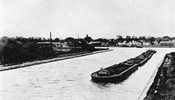
Channel circling the deep gorge at Medina, behind a wall having a maximum height of 45 feet; in effect running behind a high dam for nearly a third of a mile. The outer face of this wall appears in the distance; in part it flares to an overhang, giving a top width of 15 feet for a passageway. To compensate for sharp curvature the channel reaches a maximum width of 300 feet. Frame terminal warehouse at the extreme right.
Because of the difficulties involved in the problem of crossing Oak Orchard creek in the village of Medina, a short stretch of canal in this vicinity became one of the most interesting portions of the whole line and received a greater amount of study than any other section. The old canal passed this locality by following a sharp horseshoe curve. Just below the canal crossing the creek descended a steep declivity and its valley widened into a gorge which, at the point where a direct line would cross it in connecting the straight stretches of canal on either side, was 500 feet across at the top and 90 feet deep.
To have carried the new canal across this gorge would have secured excellent alignment, but the plan involved serious difficulties. All of the early studies, however, contemplated some method of crossing along the straight line. Soon after the Barge canal was authorized, two tentative schemes were considered. One was by means of an earth fill, on which was to be a channel of standard embankment section. This plan gave an extremely wide fill and was not given very serious consideration. The other method was by means of a steel trough supported by steel trestlework resting on concrete piers. Plans along these lines were not worked out so carefully as were those of the later studies. When, after a little while, the consideration of this locality was begun in earnest, complete plans and estimates were made for seven schemes. A comparison of these methods and their relative costs is of interest, especially to the engineer, since it shows the advantages of a concrete over a steel structure and also that both of these are cheaper than an earth fill.
The seven schemes and their costs, which included simply the length of canal across the gorge, were as follows: (1) A steel cantilever structure with a steel trough for the canal, which was estimated to cost $500,000. (2) A three-hinged steel arch of 300 feet span, center to center, carrying a steel trough for its length of 300 feet, the approaches of about a hundred feet on either side being concrete troughs supported on short concrete arches. The estimated cost was $405,000. (3) The same steel arch and trough, but with approaches built all of steel, the cost being $407,000. (4) A concrete arch in place of the steel arch, the remainder of the structure, both trough and approach supports, being of steel, at an estimated cost of $300,000. (5) An all concrete structure, consisting of an plain concrete trough on a concrete arch of 300 feet span, center to center, which was estimated at $272,000. (6) The same concrete structure, but with architectural adornment, which would raise the cost to $285,000. (7) An earth fill over a long culvert, the canal to be carried in a concrete trough, estimated to cost $433,000.
After careful consideration the sixth scheme was adopted for making detail plans on which to let a contract. The reasons for the choice were, briefly, that this concrete structure was considered to be the safest, most permanent, cheapest to build, the cheapest to maintain and the most pleasing in appearance. Complete contract drawings were made and for some time it seemed that the canal would be build in accordance with these plans. In developing the plans the arch was made a little shorter than in the tentative scheme. The dimensions of the proposed structure, however, are given in the chapter on canal construction and need not be repeated. A full description is given there also of the careful tests made on model arches in order to ascertain beyond doubt, before undertaking construction, that so novel a venture would not fail. It was told too that, although the tests proved the stability of the structure, it was finally decided to build the new canal along the old alignment.
But before this final decision was reached another scheme was considered, that of crossing the gorge on a rock fill. This fill was to be made of quarry spalls, which could be obtained cheaply from near-by. On its top there was to be a cushion of earth and a concrete trough backed by small earth embankments. The estimates showed this project to be about $90,000 cheaper than the concrete arch, but plans were never worked out in careful detail.
The canal as it finally was built in this vicinity embodies several interesting engineering features, the most important being the long stretches of retaining wall, some of it unusually high, and the aqueduct over the creek. Although the extent of the canal under this contract was only two and a third miles long, there was on the north side one continuous stretch of retaining wall nearly seven thousand feet long while on the south side two pieces together measured about forty-six hundred feet. Between fifteen and sixteen hundred feet of the north wall was high, extending in some places well below canal bottom, to the natural surface as it sloped down toward the gorge. Here the bed of the canal is a rock fill and the wall beside the channel sustains hydrostatic pressure for its full height, which reaches a maximum of 45 feet. Thus in effect the canal runs behind a high dam for nearly a third of a mile. As a preventive against leakage at this high wall a vertical plate of steel was embedded six inches in each of two adjoining sections at the joints formed in construction.
The aqueduct, while it is not spectacular like the proposed long structure and has a span of only 50 feet, still is the longest aqueduct on the new canal. The arch ring has a thickness of three feet at the crown and of 6 feet 10 1/2 inches at the springing line. The rise is 12 feet, the radius of the intrados, 32 feet, and that of the extrados, 49 feet. The clear width of channel between side walls is 125 feet. So as not to interrupt navigation the old aqueduct had to be torn out and the new one built in one winter season, and of course concrete had to be kept from freezing until all danger of injury had passed. An outstanding feature of this structure was the care taken to prevent leaks. Steel plates similar to those used in the high retaining walls were embedded at all joints, both those between the several arch rights and those between the rights and the side walls or the skew-backs. Also the top of the arch was covered with a waterproofing of tar felt and pitch which was joined to the side walls in a rather novel fashion, to prevent it from cleaving off. Into rectangular grooves left in the side walls a few inches above the arch the edges of the waterproofing material were tucked and then the grooves were flush filled with concrete.
The descriptions of engineering features connected with the Barge canal could be continued interminably and perhaps with profit to an interested engineer, but those already cited must suffice for the present volume.
1 Excerpt from letter of Major C.O. Sherrill.
http://www.eriecanal.org/Texts/Whitford/1921/chap23.html