Comparisons with Old Machinery and Methods -- Bridge Type of Conveyor -- Tipple Incline -- Hydraulic Disposal Boat -- Tower Scraper -- Aerial Conveyor -- Double-Boom Conveyor -- Cantilever Crane -- Ladder-Dredges and Belt Conveyors -- Hydraulic Dredges -- Rock-Breaker -- Belt Conveyor for Mixed Concrete -- Floating Concrete-Mixer -- Cableway Concrete-Conveyor -- Tower Concrete-Distributor -- Bank-Sloper -- Instance of Wide Variety of Machines.
In many ways the world's greatest progress has been made in recent years. This is especially true of the mechanical arts. The huge and powerful machines which today are building our public works are so familiar that we have ceased even to notice them, but we do not have to go back very far in time to find the work they are now doing being done by armies of navvies. The original channel of our own Erie canal was dug with pick and shovel, plow and scraper, and indeed the plow and scraper were considered marked improvements over the more common tools. In the report of the Canal Commissioners to the Assembly in 1818 we read, "It has been ascertained that much labor in excavation is saved, especially in dry ground, by the use of the plow and scraper;" this in comparison with "the European method with the spade and wheelbarrow."
The Commissioners continue, "And even with the spade and wheelbarrow, more progress can be made in excavation, than was supposed. As an exemplification of this remark, the commissioners state with the fullest confidence, on the authority of Messrs. Pease, Mosely and Dexter, that three Irishmen in their employ, finished, including banks and towing-path, three rods of canal, in four feet cutting, in the space of five and a half days. Thus sixteen and a half days' work accomplished the excavation of two hundred forty-nine and one-third cubic yards."
But we do not have to go back to the first building of the Erie canal to find even more primitive methods. A half century ago the Suez canal was completed. During its construction Count de Lesseps' ally, the Viceroy of Egypt, drove the wretched fellaheen by tens of thousands, under the broiling sun, to scoop the sands of the desert with their naked hands, to be carried upon their heads, under the lash of the overseer, to the spoil-bank. At night the tired bodies of these workers rested on the adjacent bank without protection. The cruelty and the consequent high mortality of these methods, however, at length attracted attention and drove Europe to rise in protest, and more modern means completed the canal.
In the present chapter we desire to notice briefly some of the machinery used in constructing the Barge canal. It is no more remarkable, of course, than that used on other large modern undertakings, but in comparison with the methods employed on earlier canals, as we have just seen, it becomes interesting. Moreover, like all enterprises of size, the Barge canal has developed some distinctive machines. Its prototype, the original New York canal, was the first large public enterprise in America. When this early waterway was begun there were virtually no engineers and no contractors in the country and machinery for such works was still to be devised. As showing the long road we have traveled between the two canals it is instructive, before we consider the modern machines, to see what beginning the early canal-builders made toward modern methods. To quote the History of the Canal System of the State of New York:
"In prosecuting their work through the forests the contractors were in need of an easy means of grubbing and clearing and their ingenuity was equal to the demand. Their inventions, though somewhat primitive, were a long step forward and are interesting as the precursors of modern contractor's machinery. Three of them are deserving of notice. By means of a cable attached to the top of a tree and wound on a wheel worked by an endless screw, one man was able to fell the largest trees. A machine for pulling stumps was made of an axle, twenty inches in diameter and thirty feet long, supported on wheels sixteen feet in diameter; midway on the axle was fastened a third wheel of fourteen feet diameter. When the outer wheels were braced, a chain wound about the axle and fastened to the stump, and horses or oxen attached to a rope which encircled the central wheel several times, a stump was easily pulled and then carried away by the same machine, after the outer wheels had been released. The gain in power was such that, with one machine, a team of horses and seven laborers, from thirty to forty large stumps were grubbed in a day. A plow with an additional cutting blade was invented for use among small roots."
The Barge canal has been built almost entirely by contract. Although the contracts were usually awarded to firms already having large plants, the nature and magnitude of the canal work seemed to call in many instances for specially designed machines. Moreover, because of the inaccessible locations much of the equipment had to be erected at the sites of the operations. The aggregate cost of all the machinery purchased and built for constructing the Barge canal is exceedingly large, running into the millions and probably into the tens of millions.
The largest single machine on the canal was a conveyor of bridge type, used in excavating the deep rock cut near Rochester. This was an adaptation of machines used for handling coal and ore but probably this was the first instance of its use for conveying excavated material. The depth of cut and the elevation of the spoil piles at this locality required a machine which would lift its load of broken rock from 70 to 80 feet, free and clear of all intervening machinery or obstructions, and swing it rapidly well beyond either bank. It had to be sufficiently mobile also to enable it to travel along the line of the canal. The machine built to meet this situation was of huge dimensions. The ordinary heavy, steel-truss, double-track, railway bridge of 100 feet span passed underneath its bulk without obstruction and was dwarfed by the comparison. A man standing beside even the bucket of this machine looked like a mere pigmy. The machine consisted of a bridge of cantilever type supported on two steel towers, one on each bank. Suspended from a trolley car running on the lower bridge chords were an operator's cabin and an immense grab bucket. The bridge measured 428 feet from end to end, the cantilever overhang being 128 feet beyond one tower and 96 feet beyond the other. The towers stood 90 feet high and ran upon parallel tracks. The structure weighed approximately 660 tons. The jaws of the bucket, 10 feet in width, stood 20 feet apart when fully open; its weight, empty, 21 tons; the full capacity of its bite, 12 cubic yards. For a time a large steam-shovel worked in conjunction with the bridge conveyor, loading two 12-yard skips, but it was found that by blasting the rock to smaller fragments the grab bucket could work to as good advantage. The operations of the trolley and the bucket were under the control of a single man. From his window in the trolley-cab, a hundred feet perhaps above the blasted rock, he would let the bucket swoop down like a monster bird of prey, bring it to a stop just above the surface and then let it settle gently upon the desired spot. Slowly but irresistibly the jaws would close, crunching through the rock and engorging a huge mouthful, and then the tons of broken fragments would be quickly swung aloft and out through the tower portals to the end of the bridge, where they could be dropped on the growing rock piles. Before the last of the rock had reached the pile the bucket would be on its way back for another load, making the complete cycle of operations in from a minute and a half to two minutes.
On the upper portion of this rock cut near Rochester a simpler type of machine was used. This was known as a tipple incline. It was not used for excavating but simply for conveying the rock to the spoil piles. A steam-shovel filled the two cars that ran alternately up inclined tracks and were dumped by being tipped forward over the apex of the incline. A movable extension at the foot of the incline permitted the cars to go down into the cut within reach of the steam-shovel. The whole machine could be moved on tracks parallel with the line of the canal. This type of conveyor was not very common on the canal but several of them were in use.
The material in the bed of a certain portion of the Mohawk river gave rise to a somewhat unique contrivance. Although most of the several parts of this device had been used in other machines, the combination was peculiar and it was the first of its kind. On its side it bore the name, "Dredge No. 3, Canajoharie," but really it was no dredge at all. It became known quite generally as the hydraulic disposal boat, but this name is too indefinite to carry any idea of its nature. The conditions of its building were these: The contract was one for excavating from the bed of the Mohawk river material which, except for the presence of a rather large percentage of sizeable stones and boulders, might have been handled by a hydraulic dredge. According to the specifications the contractor, if he did not remove boulders to the spoil-banks, might bury them in the bed of the river, but their tops must be at least two feet under the finished bottom plane and no compensation except for excavation to grade would be allowed. There was not sufficient space in the river to allow of dumping by scow. The only remaining course, the contractors concluded, was to segregate the boulders and send the rest of the material ashore by the hydraulic method. This plan had the advantage of permitting these large stones to be placed along the banks where the handling would be easy and also where they would serve the useful purpose of preventing scour. The disposal boat was the instrument for accomplishing the several parts of this process. In brief it screened out the boulders and placed them in scows for towing ashore, but the bulk of its work was to pump the gravel, the sand and the smaller stones through pipes to the spoil-areas behind dikes built to hold the solid materials while allowing the water to drain back into the river.
In its entirety this excavating unit consisted of the disposal boat, two dipper-dredges, an attendant tug, scows for carrying the boulders, a small dredge with orange-peel bucket for unloading the scows, and apparatus for building the dikes. The disposal boat was the only part not of standard design.
The hull of the disposal boat was 110 feet long, 38 feet wide and 7 feet deep. The dipper-dredges operated one on each side, depositing their spoil in a hopper at the forward end of the boat. The hopper consisted of two parts, each receiving the output of a single dredge. Each part was a steel-lined table with raised sides and sloping toward a central chute. A constantly shaking motion, towards and away from the chute, was imparted to the tables, and this motion, together with four jets of water at the top of each table, gradually forced the material into the chute, the object being to retard its advance just enough to distribute the load more evenly on the pump that finally put the gravel and smaller stones ashore. The chute was also steel-lined. Here a downward slope and another jet of water moved the material into a revolving screen. This screen was 22 feet 8 3/4 inches long and 6 feet in diameter, mounted on four friction rollers, two of which were used to drive it. It was made of the best manganese-steel castings, built up of three sections longitudinally, each having five parts to form the circumference. The castings were about an inch and a quarter thick, reinforced by ribs and bolted together. The perforations were 7 1/2 inches square, with rounded corners. Between the longitudinal sections, baffle rings, three or four inches wide, projected inward. Beneath the screen was a sump, into which the material passing through the openings fell, aided by a final jet of water introduced at the upper end of the screen. This sump was directly open to the outside water, so that the pump might never suck air, even if its supply of dredged material were too long delayed. The pump itself was set at the extreme stern, connection being made with the sump through a 10-inch suction pipe. The material rejected by the screen rolled down into a skip, which was suspended from an overhead truck that ran on a track extending beyond the sides of the boat the width of the rock scows. One end of this skip could be elevated to dump its load. The skip discharged into scows on either side, according to convenience, the dipper booms of the dredges being long enough to reach the hopper with a scow between the boats. The overhang of the track could be drawn up to a vertical position when not in use.
The pump had a discharge pipe of the same size as the suction pipe -- 20 inches. The pumping plant was calculated to discharge its material 28 feet above the water-level at a point 1,600 feet distant, provided no angle in the pipe exceeded 20 degrees. If no more than five feet in elevation were required, the length of the pipe could be increased to 2,400 feet.
The crew for this disposal boat consisted of an engineer and an oiler in the pump room, a fireman and a coal-passer in the boiler room, an engineer to run the 12-inch pump, an engineer in the pilot house, another engineer and one or two boys to operate the skip, and two or three deck-hands.
There was one type of combined excavator and conveyor which distinctly owed its origin to Barge canal work, having been conceived by one of the contractors' superintendents. To this was given the name, tower scraper. It was a device consisting of a simple frame tower and a hoisting engine mounted upon the same base, which operated a scraper bucket, the carrying cable running to a fastening that slid on a cable anchored at the farther side of the cut. By making the tower tall enough its range of operations could be increased to several hundred feet. At first this machine was used chiefly in diking, but later its field was extended to general excavating in shallow cuts and it was installed on many contracts. A variation on one contract was the use of two towers with cables between, standing on opposite sides of the canal cut and each operating its own bucket.
A somewhat similar device, but in this instance an adaptation of a conveyor found in a Vermont quarry, was used on one of the Champlain canal contracts. This was a conveyor simply, operating skips, the excavation being accomplished by other means. It was used in a rock cut and the blasted rock was loaded into the skips largely by hand. For the want of a better name it was called an aerial conveyor. It consisted of a high mast, set at the far edge of the spoil-area, with a series of cables running from the top of the mast to the several near-by places where the rock was being excavated. A small and rather ingeniously equipped car ran on each cable and these cars raised, lowered, carried along the cables and tripped the skips. This rather simple and inexpensive device served the need of its particular locality, where the rock cut was of small extent.
Where long stretches of canal were to be chiseled out of the rock, conveyors of a sturdier type were generally employed. An unusual member of this class was the double-boom conveyor on the section just west of Lockport, where, perched high on the bank with its two long arms upstretched, it became a memorable sight. It was patterned after one of the most common machines on the canal, the excavator which revolved on a circular track and had a long boom that carried a bucket, generally of the drag-line, scraper type. This latter machine could scoop up a bucketful of earth and then swing around and deposit it at a considerable distance back of the prospective bank line. The double-boom conveyor was an adaptation of this scheme, but its peculiarity lay in two features. It was a conveyor solely, its booms carrying only skips, and it had two booms instead of one. It was fed by a steam-shovel, which followed in the wake of batteries of channelers and drills. The two booms were set opposite and while one skip was being loaded the other was being dumped. The contractor estimated that the time saved by having a skip in position for loading almost continuously, without stopping to attach and detach or to dump it, was of sufficient value to pay for the extra cost of a machine of this character.
Not far from the double-boom conveyor there was another interesting machine, which, however, was operating in earth and was both an excavator and a conveyor. This was a cantilever crane and it resembled somewhat the bridge conveyor, although it was of much lighter and less expensive construction. It was supported by a single, central, steel tower, which traveled on the berme bank of the canal. The excavating arm stretched across the canal to the tow-path, while the dumping arm reached back of the berme for a considerable distance, so that the spoil could be deposited well back of the bank. Operations were controlled from a stationary house at the tower, and the car, which ran on the lower chord, carried a scraper bucket. The superstructure was inclined some twelve degrees from the horizontal, dipping down toward the material to be excavated and rising above possible obstructions at the land end. This machine worked in both wet and dry material, when the water was in the canal in the summer and after it had been drawn in the winter.
Another type of machine we should notice is that called the ladder-dredge, the bucket-dredge or the elevator-dredge, all three names being applied to the same machine. But no claim for novelty can be made for this dredge or even for the combination used on the canal, that of ladder-dredge and of belt conveyor for carrying the spoil ashore. The most conspicuous of this type of dredge were the two on the contract which extended west from Oneida lake for about 42 miles. Two kinds of delivery belts were used on this contract.
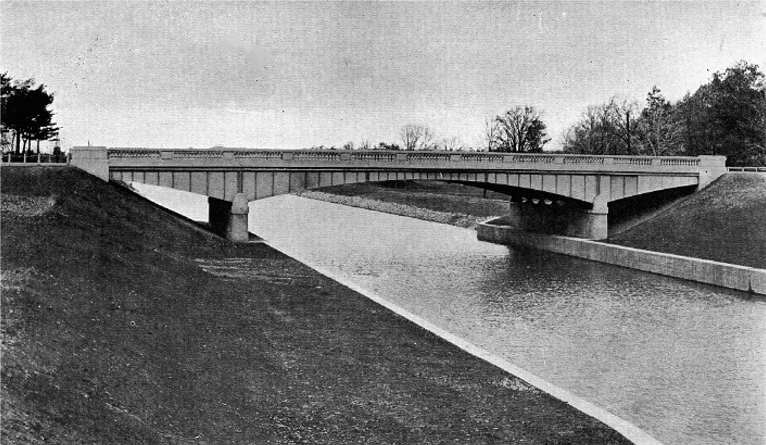
Channel in Genesee Valley park, Rochester, where to prevent despoiling the beauty of the landscape, structures of artistic design have been built, dikes and drains have been placed to preclude overflow and carry away seepage, and spoil-areas have been transformed into pleasing lawns.
By one combination a dredge and a boat carrying a belt conveyor worked together and delivered the excavated material into scows, which were towed out into deep water in the lake, where they were dumped. By the other combination the dredge, an intermediate boat and a boat carrying a shore delivery belt were able to deposit the excavated material a hundred feet inshore at any desired height up to sixty feet above water and then to wash it still farther back some thirty feet. This machine also, with material dropping from the belt high in the air and so far from the shore line, presented an unusual sight. Another ladder-dredge, accompanied by a belt conveyor boat, was used for excavating in the channel west of Rochester. Here the new canal coincided with the old in alignment and the shore conveyor portion was of sufficient length simply to place the spoil back of the tow-paths or berme banks.
From these descriptions it will be noticed how important were the devices for disposing of excavated material. In the construction of the Barge canal, as in any large enterprise of like nature, the problem of conveying excavated material to spoil-banks was often more perplexing that that of digging it and also involved greater expense. In addition to the conveying machines already described many ordinary and less spectacular methods were in daily use. The most economical way of handling much of the material was by means of hydraulic dredges and many such machines were on the canal. But these dredges were nearly all of standard type and call for no special description. One or two of the first of those to be put on the canal were peculiar in having cutters which revolved on a vertical rather than a horizontal axis, but the innovation did not prove very successful. Most of the suction dredges on the canal were of the 20-inch size. Some of them made good records; for example one had a little more than a half million yards to its credit for a month's work. In comparison with the boast of the early canal commissioners mentioned at the beginning of this chapter the amount is interesting. This dredge for a month was excavating as much material every 17 minutes as the three men together could dig in five and a half days. Or to put it another way -- the dredge accomplished as much in one minute and two seconds as one of these men did in a full day.
A machine of quite different character, neither excavator nor conveyor, was the rock-breaker. This was a device for loosening subaqueous rock. In some places where there was rock to be excavated in the beds of rivers long stretches of the stream were cofferdammed and the work done in the dry, and in other places the material was drilled and blasted without being uncovered, in the latter case a boat carrying a battery of drills and operating engines being used, but in a few places the more unusual machine, known along the line of the canal as a rock-breaker, was employed. The principle of this method was that of loosening the rock from its bed by the impact of heavy blows. The shattering was accomplished by dropping from a considerable height a cylindrical hammer, 26 feet long and weighing between 15 and 16 tons. At the lower end of the hammer a removable section, in shape a conical point, could be renewed when worn out. The machinery was all contained within a boat that was held in position and moved by means of wire cables, anchored on shore. It was customary in operating with this device to move back and forth so as always to be working against a face of unbroken rock. After the rock-breaker had finished its work the broken fragments had to be removed by a dredge.
All of the machines thus far described have been in some way connected with the excavation of the channel. But from both an engineering and a popular point of view the structures on the canal are more interesting than the channel. When it came to furnishing machinery for building the structures, however, there was less opportunity for developing anything peculiarly striking or novel. But on one contract there was produced an appliance for conveying mixed concrete which was both striking and novel. Three locks of the Waterford series were built under this contract. These structures are all unusually large and also they are in close proximity, there being a distance of less than two thousand feet from the central lock to the farther end of either one of the other two. The economic handling of concrete in building large structures is a matter of importance of course on all occasions, but in this instance, because of the exceptional amount to be handled and the possibility of reaching all three locks without going far from a central mixing plant, the problem became one of uncommon moment. The solution in this particular case took the form of a plant in which belt conveyors did all the work of transporting materials, both before and after the concrete was mixed. Although belts had been used before for conveying materials to a mixer, this was probably the first instance of their use for carrying the mixed product to the place of deposit, at least for any considerable distance, and so the device was of especial interest.
A concrete mixer, of the Hains type, was placed about midway between two of the locks, at the center of distribution of approximately 100,000 yards of concrete work. Beside the mixer were railroad tracks of sufficient capacity to hold cars for supplying materials for 500 yards of concrete a day. The sand and stone came in bottom-dump cars, which delivered their loads through hoppers to the belts that ran to the mixer. There were bins for storing surplus sand and stone and these also were served by belts. From the cement storage house a belt ran to the mixer. All hand operations were thus reduced to a minimum. At the mixer itself a little handling was necessary; some shoveling was required in getting stone and sand from the ends of cars to the hoppers; the cement had to be carried into the house and then lifted to the belt when needed; but aside from these operations the belts did virtually all of the work.
From the mixer there extended a series of three long belt conveyors to the site of the lock, the longest being 600 feet in length. The first two conveyors discharged into hoppers, so as to feed properly to the succeeding belt and also so as to hold up the delivery of a whole or part of a batch of concrete in case of any necessity for shutting down quickly. These belts ran at a speed of about 450 feet per minute, but each succeeding one ran a little faster than its predecessor, so as to correct, especially on the long belt, any excessive loading at the mixer. The delivery at the lock was made through a huge tripper-car, which had a boom 45 feet long, carrying an independent belt. By moving this car along the length of the lock and swinging and raising or lowering the boom all parts of the work could be reached. Depending from the end of the boom swinging spouts of various lengths were used to collect particles of the concrete to a narrow space in dropping them into the forms. This latter device, with its swaying motion, proved effective for good results, for, unlike any form of bucket which discharges a large volume quickly, with an outrush of grout incident to the operation, the belt and spout deposited the concrete gradually and secured a uniform consistency throughout the mass. Water piped to the end of the boom was at hand to be added to the mixture if necessary.
In operating the tripper-car certain hand manipulations were required, but aside from this all transportation from the mixer to the forms was done by power-driven machines. Electric current, taken from near-by lines, furnished the energy at this plant. In building the second lock under this contract the tripper-car was discarded and a belt line was run over each lock wall. Moreover, the third lock was so far away that a train of cars was used between the mixer and a short line of belts.
Three or four other machines on the canal deserve a simple mention. At Fulton there was a floating concrete-mixing plant. At a lock near Rochester a long cableway bore the concrete in buckets from mixer to forms. During the latter part of canal construction there were several somewhat elaborate concrete-distributing plants of the high tower and long chute variety. These were not permitted during earlier construction, but canal work followed the trend of the time in this particular and conformed to what was then becoming a common practice. A rather novel contrivance was a bank-sloping machine, built for one of the Champlain contracts. Somewhat similar appliances were later used at other places.
Not all of the machinery employed in constructing the Barge canal can be said to have been eminently successful from the financial standpoint. Some of the elaborate devices cost very large sums and as they were often of novel design they received much publicity, but there is a question whether the contractor who used simpler and more usual means did not fare better.
The machinery described in this chapter is not a tithe of that used throughout the whole canal. Few well-known varieties were lacking and often widely differing appliances were employed for doing the same kind of work. This fact was illustrated most vividly on the section just west of Lockport, where a greater variety of machines was found than on any other single contract. In walking over the line the first to catch our eye would have been the usual locomotive and train outfit. Then a set of guyed derricks swung their long booms from prism to spoil. Next, locomotive cranes, working in pairs, performed the same office. Again, an inclined track, with tipple at top and mounted on a traveling base, carried its cars from canal to bank. Also there was a cableway, with travelling towers adjustable as to distance between them. Still another form was the double-boom conveyor, which could be loading and discharging at the same time. These machines were all conveyors simply and each had its complement of drills and channelers and of steam-shovel, revolving drag-line excavator or other loading or digging apparatus. In addition there was also operating on the Lockport section the great cantilever crane, extending from the tow-path to the spoil-bank behind the berme. But variety of machinery is not the theme of this chapter. Rather the purpose was to describe noteworthy specimens and the most conspicuous of these have new been mentioned.
http://www.eriecanal.org/Texts/Whitford/1921/chap26.html